Tuesday, April 6, 2010

6th April 2010 Seat modifications

I picked up some seats from a Holden Piazza for $100

Because of the VERY small and narrow passenger compartments, most regular seats will not fit

These seats are pretty narrow, comfortable and quite "buckety" but they are still too wide by about 2 inches so i will have to narrow them.

Removed the seat runners, split the base from the back and removed the cushions and covers. The bolsters are seperate cushions and are adjustable to squeeze around your chest. There are many other adjustments on these seats but i won't need them. I will leave off the bulky adjuster mechanism and bolt a plate on the hinge instead. Will just have to make sure it's at the right angle coz i'll be stuck with it!

So with the seat stripped down i am left with the base and backrest frames.
On the backrest, i cut 2 inches out of the bottom beam and an inch out of each side at the top corners. If i had taken 2 inches out of the centre at the top, i would have had to modify the headrest aswell, but this way i can leave it as it is.

Pretty similar procedure for the base but much more simple.


5th April 2010 Rolling chassis

With the basic chassis now complete, i can assemble front and rear suspension, fit the wheels and get rollin'

Very excited to finally see it on it's wheels. A piece of plywood makes a half decent seat for messing around and making brum brum noises.


4th april 2010 finishing basic chassis

I sat the T50 Gearbox in place and measured out the rest of the transmission tunnel and set out manufacturing it. Unfortunately this gearbox is quite bulky on the driver's side so had to build the tunnel around the lumps and bumps and this brings the footwell in a couple of inches.
Chopped out the lower front and rear sections to clear the gearbox and diff.

So that's the basic chassis completed

WIKID!


16 feb 2010 start transmission tunnel


Started to construct transmission tunnel as per the book.

Shortly after starting, i realised that the 2 verticals at the rear of the tunnel in the first picture were in the wrong place. Unfortunately, the correct position is not clearly stated in the book. They are supposed to be 25mm further out to accommodate the diff.

Also there was another fault in the book. The "dogleg"in the lower rear right portion of the tunnel is stated as 12" from the rear but this is incorrect. This measurement is for the top portion so the real measurement for the lower is about 8".


Feb 2010 Painting Escort Rear Axle

Finally decided to buy myself a HVLP (High Volume Low Pressure) Spray Gun
It's a lot like a regular spray gun but instead of spraying a lot of paint with a lot of air, it uses a lot less air so more paint hits the workpiece. Less overspray and more economical.
Even with the thick "chassis black" paint, i still got a pretty good finish


Monday, April 5, 2010

14th Feb 2010 Rear corner detail

he book says that at the rear corners, you should bend a very tight radius in 19mm round tube - which is much easier said than done!!!
Instead, i decided to use 3mm steel strap 25 mm wide. I bashed in the radius and it looks great so welded it on. Doesn't have to be strong as not structural it just has to be neat as the aluminium sheet at the rear wraps around it.


Feb 2010 Front suspension assembly

Pretty self explanatory here. A painstaking process of clamping, measuring, adjusting, measuring, tweaking and tack welding.
A useful tip here: After heaps of messing around i decided to use 2 lengths of steel drilled at each end at the right spacing to locate the top mounts the right distance away from the bottom ones.You can see this in the second photo.


Jan 2010 Lower wishbone construction

I cut out the large hole in the plates on the lathe by centring and welding the plate onto a piece of tube and then turned out the hole to the right size
I also turned a plug to the same size which could be used to centre the plate on the jig.
Again, the jug was fabricated to book specifications and taking into account the size of my bush tubes.
The plates and bush tubes were clamped and bolted to the jig and the tubes cut to length and shape and welded together.
As these wishbones are symetrical, i could weld one side, let it cool and turn it over, clamp and weld the other side. Very happy with the result.


Jan 2010 Lower wishbones - plate fabrication

For my lower wishbones, they are significantly more complicated than the upper ones.
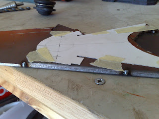
First i drew out my wishbone design full size on card and then when i had my design in full scale for the plate, i traced it and transferred it onto card. 
I then welded together 2 pieces of 4mm steel plate and taped on my cardboard template.
Then using the template as a guide, i used the bench drill to drill the hole centres and punch holes around the outline. Once i had finished all the drilling, i could cut out the basic shape more easily with a cutting disc on the grinder. Then just tidied up the edges with the flap disc and seperated the 2 plates apart.


Jan 2010 Upper wishbones

Top wishbones.
I started by making a jig to the size and specifications stated in the book and using the dimensions of my bush tubes
Once the jig was made, i fitted in my bush tubes and the threaded tube to hold my top ball joint and then cut and welded the support tubes to suit. 
DONE!